This tool is used to semi-automatically compute parameters for the Proxel Lens Corrector tool; a tool that corrects distortion in images.
You take images of long straight objects, e.g. plumb lines or door posts. The tool runs edge detection to detect those straight objects and then computes correction parameters for keeping those lines straight in the image. The same correction parameters can be used to straighten up any image. The parameters are stored in Lens Corrector Project (.lcf) files. For zooms, the file contains several focal lengths and the Proxel Lens Corrector interpolates for intermediate focal lengths. When available, EXIF information is used for determining focal length.
For rectilinear lenses all straight lines shall be straight in the image. This tool is based upon that property.
In the Proxel Lens Corrector the coordinate system is chosen so that the unit length is half the width of the image. The origin is in the middle of the image, x is to the right and y is down. For consistency for radial parameters (k1, k2, fish_r) we assume that the image is in landscape format. For consistency for offset parameters (xc, yc) we assume that the image is not rotated upside down.
Radial distortion is commonly modelled using a polynomial with only
odd powers of the radius (*). The coefficient for
r1 is unnecessary.
rimage =
rorig1 +
k1 * rorig3 +
k2 * rorig5.
The lens might be offset to the center of the sensor.
ximage = xorig + xc.
yimage = yorig + yc.
Fish eye lenses are normally equidistant, i.e.
rimage = fish_r * (2.0 / PI) * alpha.
( where
alpha = atan((rorig / fish_r) * (PI / 2.0))
)
This means that an 180o fish eye has the image radius equal
to fish_r.
------------
(*) Note that the popular freeware "panorama tools"
have a non optimal formula for distortion as it lacks the
r5 component. In practice it contains
only the r3 component.
rimage =
a * rorig4 +
b * rorig3 +
c * rorig2 +
d * rorig1.
Many lens correctors (freeware or not) are based on this tool. This
was one of the main reasons why we wrote our own corrector and not
just wrote an analyzer that used already existing correctors.
The line detection in the Proxel Lens Analyzer is based upon a modified version of the Canny edge detector. This modified detector makes it possible to quickly switch to different thresholds and therefore quickly generate edges for different sensitivities. Furthermore, the edge detector detects only vertical and horizontal lines.
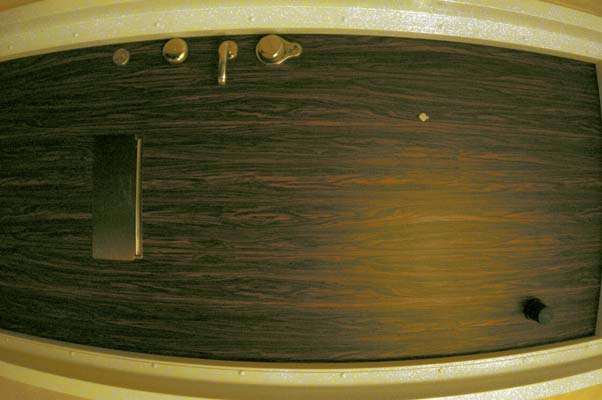
First you have to find something with long straight edges. If you cannot find anything you can always use the plumb line method, i.e. mount a string with a weight. In practice door posts can be used if they are straight enough, e.g.
It is important that the straight lines are close to the edges of the image. The lines shall also be more or less horizontal or vertical. In general, you don't need lots of lines. Sometimes even one line is enough if you don't want to detect offset. The lines shall be long though. The lines can be taken from one or more images.
NOTE – the images do not need to be sharp. Actually – the line detection algorithm does its own unsharpening. So – even if photographing something rather nearby – set the lens to infinity.
BEWARE of shadows in the images. The detected edge might not correspond to the actual edge – we have found that this is most evident when using strings, i.e. the plumb line method. Even illumination is also best.
If you want to detect the offset parameters, it is also important that you have straight lines on both sides, i.e. if you want to detect yc, you need lines both above and under the center and if you want to detect xc you need lines both to the left and to the right of the center.
The Proxel Lens Analyzer can read several file formats, but not RAW formats. It is advisable to use e.g. JPEG or TIFF.
BEWARE that some cameras (e.g. earlier firmware for Pentax *ist) may have different image size for RAW and JPEG, which might result in needing different parameter values for shooting RAW and JPEG.
In general you create one project for each lens/camera combination. For cameras with fixed lens (e.g. compact cameras) this means one project per camera.
If you have several camera bodies (with different size sensors) that can use the same lens you can either measure for each camera body or you can simply transform the project (if you know the sizes for each sensor), using the calculator included in this document. The projects are text files that you can edit with the new values.
Your project is managed in the Manage Project tab.
When you start the program or when you choose from the menu, you have an empty project. You can also import an existing project by choosing from the menu. You can save your current project by choosing from the menu.
To add images to the Image File table you use the button . Every time an image is loaded with a new focal length, an entry in the Focal Length table is added.
NOTE that if the image file contains no EXIF data for focal length, you will be asked for the actual focal length. For fixed focal length lenses it is possible to give 0.0 as focal length. This can be useful if you e.g. don't know the focal length.
You can remove images from the Image File table by selecting the image and using the button .
NOTE that adding and removing images to the Image File table does not affect the project.
Focal lengths are added to the Focal Length table either when loading images or when loading a project. The status of focal lengths can be either INVALID or OK.
Newly created focal lengths will have the value INVALID and focal lengths copied from a project file or from an optimization will have the value OK. You can also toggle the status with the button .
You can remove focal lengths from the Focal Length table by selecting the focal length and using the button . All images with this focal length will also be removed from the Image File table.
When saving a project, only focal lengths with status OK will be saved.
Some data is saved in the project file. This data can be filled in in the Info stored in project file fields. All fields are optional and may be left blank.
The correction parameters are optimized for one focal length at a time. The described method below is repeated for each focal length and when all focal lengths are ready, the project file may be saved.
In the drop down menu Current Focal Length you choose the focal length you want to find correction parameters for. When you choose a new focal length, the image files are filled in in the Current Image drop down menu.
NOTE – the GUI may automatically jump to the Choose Lines from Images tab when choosing focal length.
NOTE – the chosen lines and the last optimization parameters are restored when choosing a focal length again.
When you have chosen a focal length, you can choose one of the files from the drop down menu Current Image . When you choose an image, the edge detection algorithm kicks in, so it may take some few seconds for the initial analysis.
Normally you don't have to use this tab as a well taken image should work without tweaking. But if you go to the Edge detection settings tab you will see something like this.
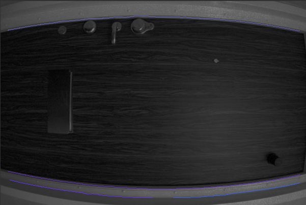
A dark image with some blue lines. The blue lines are detected edges. If you look at this particular result you can see that the lines are somewhat too short and the upper line is not really even enough. But ... it is a good try. This is how the image could be improved:
Even though the image is not perfect – let us try to find the parameters for optimization.
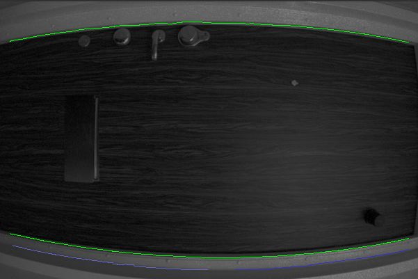
Now switch to the Choose Lines from Images tab. When moving the mouse pointer over the image you can choose highlighted lines by clicking the left button. In this image two lines are chosen – the chosen lines are green.
NOTE – the nearest line is highlighted – so there is no need for aiming exactly at lines. If no line is highlighted – move the cursor and some line will be.
Now switch to the Optimize parameters tab. By default the k1 and k2 parameters are ticked. This is the setting you shall use in 9 cases out of 10. Now you can just use the button . The result for such a simple image will be computed in a fraction of a second. In this case it will be k1 = -0.16 and k2 = 0.022.
Now you can (as an option) use the button and you will see something like this.
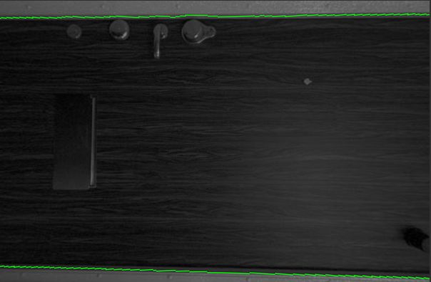
A side note is that this really is a fish eye lens (the Zenitar) and you should have computed the fish_r parameter instead. If you used the Zenitar on a 35 mm full frame camera it would have been necessary. The image also has a slight offset which should have been treated by also computing the xc and yc parameters. More about this below though. The example shows that you can get a rather good result with a non optimal image and optimizing using not optimal parameters.
When you are satisfied with some optimized parameters you can save them by using the button .
BEWARE that optimization results are not saved automatically.
In general it is not easy to find if the center of the lens has any offset to the center of of the sensor. It is not a well posed problem to try to find such an offset from analyzing straight lines. In practice it is only possible to find any reliable offset for lenses that have a large distortion, e.g. fish eye lenses or some zoom lenses at maximum wide angle.
Fortunately (for the same reason) any offset for lenses that do not have large distortion is not important for the efficiency of the corrector.
So we recommend that you by default don't optimize the offset parameters. In practice it is probably only important for your fish eye lenses.
BEWARE that if you optimize the offset parameters it is important that you have the same orientation when correcting as when analyzing.
For fish eye lenses you shall activate optimization for the fish_r parameter. By default you shall also turn off optimization for k1 and k2. You might get a better result if you have all three turned on though – which is the case if the fish eye has distortion. It might be necessary to optimize the offset parameters xc and yc. Some experimentation to get the best result might be necessary.
By default you should make all measurements with the lens focussed at infinity. But – for higher precision (at least with some lenses) you may have to make several measurements for several distances.
NOTE – unfortunately EXIF information do not contain info about focussing. So – you are basically on your own and have to choose different project files manually.
There are several possible work flows which is rather straight forward to find out after a while. But – to simplify when using the tool the first times we have devised a recommended workflow when creating a new project.
As a kind of Wizard we have enumerated (with red numbers) some of the buttons and tabs 1, 2 and 3. The step 3 is also divided into four substeps 3a, 3b , 3c and 3d
In this step you add all images to the project, i.e. for your camera (and lens if it is a camera with interchangeable lens). If it is a zoom, you add images for all focal lengths.
In this step you fill in the three info fields describing the project. The lens field is not necessary if it is a camera without interchangeable lens.
In this step you create the parameters. This step includes repeating 3a - 3d for all focal lengths.
NOTE – we recommend that you save the project after each focal length optimization round. It is irritating to have to do repetitive work over again.
In this substep you choose focal length you want to optimize. For non zoom lenses there is only one focal length.
In this substep you choose all the lines (within the current focal length) that shall be straight. You repeat this for all images (Current Image) of the current focal length.
NOTE – it might (very rarely) be necessary to change edge detection settings to get nice lines.
NOTE – it is very important to choose long lines! If you cannot get long lines, it is better to take new calibration photos.
In this substep you run the optimization. In most cases you only optimize k1 and k2. For fish eye lenses you optimize fish_r.
NOTE – the parameters xc and yc are hard to find if the distortion not is very large, i.e. a fish eye lens.
In this substep you store the parameters in the focal length table.
The parameters are computed relative to the sensor size, i.e. the unit length is half the width of the image. This means that the parameters change when the width of the sensor changes. This is of course irritating – but the reason for this choice is to avoid that you have to know the size of your camera's sensor to use the tool. The lesser evil of two bad choices.
If we define this ratio:
R = widthnew / widthold.
we can compute the new parameter values according to these formulas:
k1new = k1old * R2.
k2new = k2old * R4.
fish_rnew = fish_rold / R.
NOTE xc and yc are not meaningful to convert when changing sensor size.
© Proxel Software HB